
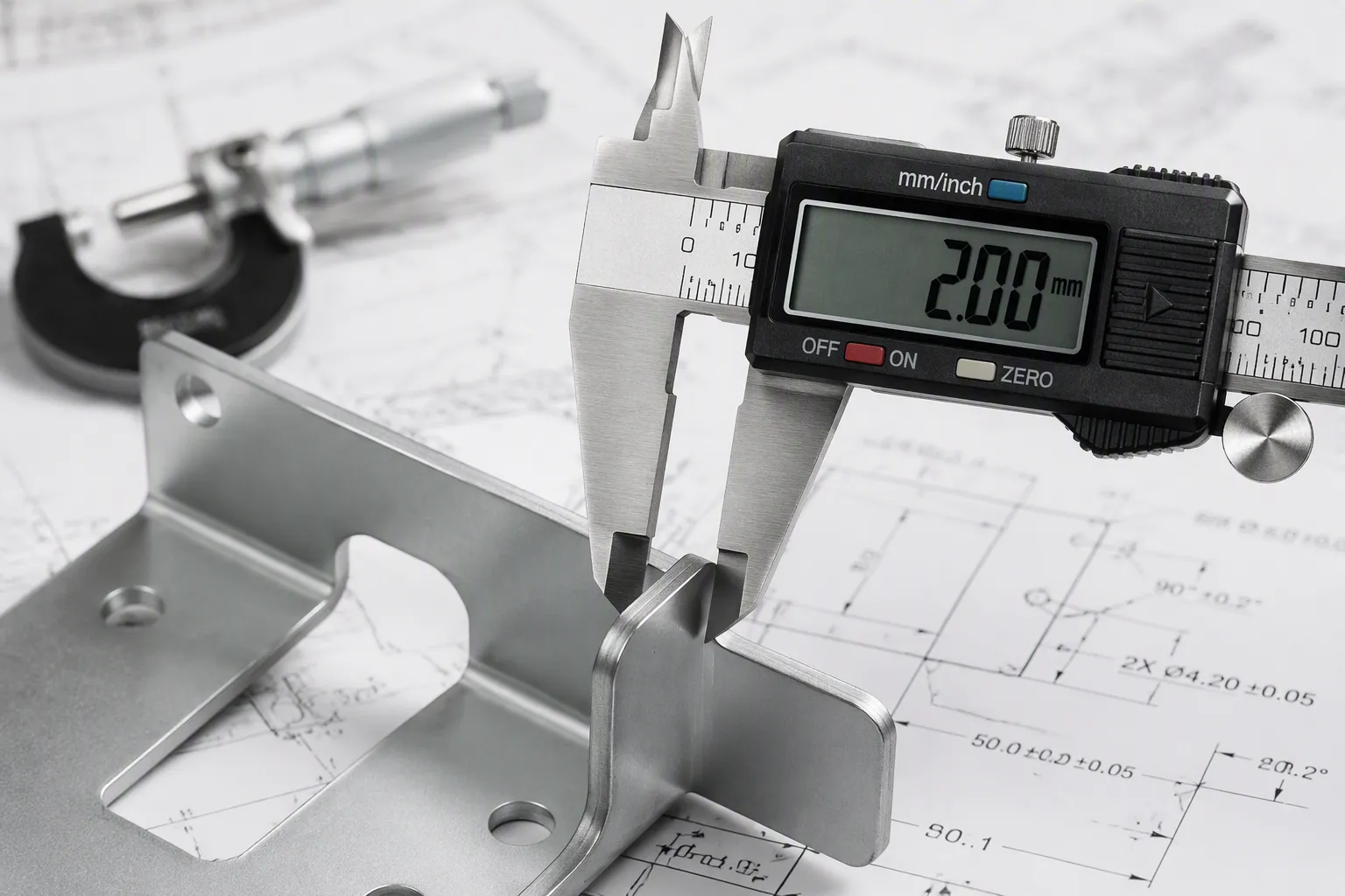
Precision sheet metal tolerances define the allowable variation from nominal dimensions for holes, bends, and edges. These values determine part fit, function, and manufacturing cost. The standard tolerance for laser-cut parts is ±0.005 inches, though material springback and tool wear affect actual results. You must balance tight specifications against cost.
Material type and thickness affect how tight you can hold tolerances. Softer metals like aluminum allow tighter tolerances than steel.
Specify tight tolerances only on critical features that affect fit and function. Use standard tolerances for everything else to save money.
Over-tolerancing increases cost and lead time without improving quality. Work with your fabricator early to set realistic tolerances.
Several variables determine the precision you can achieve in your sheet metal parts. Recognizing these constraints helps you specify realistic Sheet Metal Tolerances and avoid unnecessary costs.
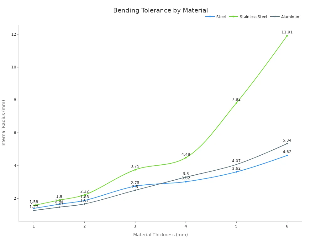
Material properties define the baseline for all Sheet Metal Tolerances. Bending is the single most important process affecting final geometry, and material type exerts the greatest influence here. Softer metals like aluminum permit tighter tolerances than steel or stainless steel. The following chart illustrates the relationship between material type, thickness, and achievable internal radius.
Sheet metal gauge is only a nominal thickness; the actual material thickness can fluctuate within the specification's allowable range. This variation becomes critically important when tight tolerances are applied to a fabricated part.
Steel requires more bending force, and thicker sheets stretch or compress unevenly along the bend line. Thinner sheets are easier to cut but more susceptible to warping during welding.
|
Cutting Technology |
Diameter Tolerance |
Edge Characteristics |
|---|---|---|
|
CNC Fiber Laser |
±0.12 mm |
Slight taper, heat-affected zone |
|
CNC Turret Punching |
±0.05 mm |
Clean vertical edges, no heat effects |
|
CNC Reaming (Post-Milling) |
±0.015 mm |
Perfectly round, burr-free |
Laser cutting offers flexibility but introduces a heat-affected zone and slight taper. Punching provides greater consistency for hole diameters. Standard commercial norms allow ±0.1 mm to ±0.15 mm for holes under 30 mm diameter.
Tooling condition directly affects achievable tolerances. Reduced punch and die clearances increase punch wear during long production runs compared to operations with larger clearances. Operators must check accumulated wear to decide whether existing tooling can handle tighter clearances. Small clearance requires additional alignment verification before every setup and operation.
Each additional operation introduces its own variance. Tolerance stackup compounds across forming, punching, bending, and assembly steps. Features placed too close to a bend line distort during forming. Bend-to-bend distance tolerance is typically ±0.381 mm. Fewer operations generally mean tighter cumulative tolerances.
Every feature on a sheet metal part carries its own tolerance range. You need to know these ranges before you finalize your drawing. The sections below break down the typical values for laser cutting, forming, punching, and welding.
Laser cutting gives you the tightest tolerances among standard sheet metal processes. A fiber laser can hold ±0.005 inches (±0.13 mm) on linear dimensions for thin materials. Hole diameters typically land within ±0.005 to ±0.010 inches. Hole position relative to an edge usually stays within ±0.005 to ±0.010 inches.
These values depend on material thickness. Thin sheets cut more accurately than thick plates. A 1 mm aluminum sheet holds tighter tolerances than a 6 mm stainless steel plate. The laser beam also creates a slight taper on the cut edge. This taper adds another variable to your tolerance budget.
The table below shows typical industry values for laser-cut features.
|
Feature |
Standard Tolerance (typical) |
Precision Tolerance (typical) |
|---|---|---|
|
Laser-cut linear dimension |
±0.010″–0.020″ |
±0.005″–0.010″ |
|
Hole diameter/position |
±0.005″–0.010″ |
±0.003″–0.005″ |
|
Bend angle |
±1.0° |
±0.5° |
|
Formed flange length |
±0.020″–0.030″ |
±0.010″–0.015″ |
|
Overall welded assembly |
±0.060″–0.125″ |
±0.030″–0.060″ |
These ranges come from common fabrication practice. They are not a guaranteed capability chart for any specific shop. Achievable tolerance depends on material, thickness, part geometry, equipment condition, and process sequence. Always confirm exact achievable tolerances with your fabricator's engineering team during quoting.
International standards provide a framework for general tolerances. ISO 2768-1 defines permissible deviations for linear and angular dimensions that carry no individual tolerance callout. The standard offers four classes: fine (f), medium (m), coarse (c), and very coarse (v). For a nominal length between 6 and 30 mm, the medium class allows ±0.2 mm. The fine class allows ±0.1 mm. The chart below compares these classes across nominal length ranges.
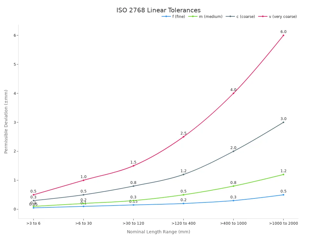
ISO 2768-2 covers geometrical tolerances such as straightness, flatness, perpendicularity, and symmetry. These classes (H, K, L) control form and orientation when you do not specify individual geometric controls. For a part up to 100 mm long, class K allows 0.4 mm perpendicularity deviation. Class H tightens that to 0.2 mm.
You should reference ISO 2768 tolerance classes on your drawing for anything function-critical. This practice removes ambiguity and gives your fabricator a clear target.
Bending introduces the most variability in sheet metal fabrication. Material springback, tool wear, and bend sequence all affect the final angle and flange length. A standard press brake holds bend angles within ±1.0°. Precision bending with specialized tooling and compensation reaches ±0.5°.
Flange length tolerances typically range from ±0.020 to ±0.030 inches for standard work. Precision forming tightens this to ±0.010 to ±0.015 inches. These values assume a consistent material lot and properly maintained tooling.
Bend-to-bend distance tolerance is another critical dimension. A typical value is ±0.015 inches (±0.381 mm). This tolerance accumulates across multiple bends. A part with four bends can see the cumulative error grow to ±0.060 inches if you do not account for stack-up.
Material thickness plays a major role here. Thicker sheets require more force and exhibit greater springback. A 3 mm steel sheet springs back more than a 1 mm aluminum sheet. Your fabricator must adjust the bend angle to compensate. This adjustment adds time and cost to the setup.
The internal bend radius also affects tolerance. A tight radius concentrates stress and increases the chance of cracking. A generous radius distributes stress and improves consistency. You should design with a radius at least equal to the material thickness whenever possible.
Turret punching offers excellent repeatability for hole diameters. A CNC turret punch holds ±0.05 mm on hole diameter under ideal conditions. This precision rivals laser cutting for small holes. Punching also produces clean vertical edges with no heat-affected zone.
Hole position tolerance depends on the machine's positioning accuracy and the part's feature count. A standard CNC punch holds ±0.005 to ±0.010 inches on hole-to-hole position. Hole-to-edge tolerances require more care. When you punch close to an edge (less than double the material thickness), the edge can be pushed out by the stress of punching the metal. Engineers should allow ±0.010″ hole-to-edge. Tolerances of ±0.005″ should be used only when absolutely necessary.
Notches follow similar rules. A notch cut too close to a bend line distorts during forming. You should keep notches at least 2.5 times the material thickness away from any bend. This distance prevents the bend from pulling material into the notch and changing its shape.
Punching requires dedicated tooling for each hole size. This tooling cost makes punching economical for high-volume runs. For low-volume work, laser cutting usually costs less because it needs no hard tooling.
Welding changes the tolerance picture dramatically. Heat input causes expansion, contraction, and distortion. These effects accumulate across the assembly and push dimensions out of specification.
The table below shows how welding distortion affects a typical butt joint.
|
Parameter / Output |
Value |
|---|---|
|
Joint type |
Butt joint (Kj=1.0) |
|
Plate thickness |
12 mm |
|
Weld size |
8 mm |
|
Weld length |
500 mm |
|
Longitudinal shrinkage |
2.67 mm (5.33 mm/m) |
|
Transverse shrinkage |
0.94 mm |
|
Angular distortion |
0.254° |
For a 500 mm weld, the longitudinal shrinkage alone (2.67 mm) can easily exceed a typical assembly tolerance of ±0.5 mm. This shrinkage forces parts out of specification unless you apply pre-positioning or fixturing.
The next table summarizes common distortion types and their effects.
|
Distortion / Shrinkage Type |
Typical Value |
Effect on Final Assembly Tolerances |
|---|---|---|
|
Angular distortion |
1° to 2° |
Causes panels to rotate around the weld joint, leading to misalignment of mating surfaces and bolt holes. |
|
Linear shrinkage |
0.5% to 1.5% |
Pulls joined sheets inward, shortening overall dimensions and potentially pushing critical features out of tolerance. |
These values illustrate that even moderate welds produce displacements exceeding common sheet metal tolerances (e.g., ±0.3 mm per bend). You cannot install slide-in rails or circuit boards without pre-compensation.
Standard tolerance for a welded assembly ranges from ±0.060 to ±0.125 inches. Precision welding with fixtures and stress relief reaches ±0.030 to ±0.060 inches. You should design weldments with adjustment features when possible. Slotted holes, shims, and oversized clearance holes absorb weld distortion without requiring rework.
Welding also introduces heat-affected zones that change material properties. These zones can warp adjacent features. You should place critical dimensions away from weld joints whenever the design allows.
Understanding these feature-specific ranges helps you set realistic Sheet Metal Tolerances on your drawings. The next section explains how these individual tolerances combine across a part.
Individual feature tolerances combine across a part. This combination creates a cumulative error called a tolerance stack-up. You must understand stack-ups to predict whether your final assembly will fit and function.
Every bend, punch, and cut adds its own deviation. These deviations accumulate across the part. A single surface may hold ±0.005 inches, but three or more bends can push cumulative error to ±0.030 inches. In one measured example, slot misalignment ranged from 0 to 0.3 mm. After evaluating three samples, engineers inferred the cumulative error on the 'L' dimension fell within 0.1 to 0.5 mm. This data shows that you must account for cumulative tolerances when you assess the precision of fabricated sheet metal parts.
|
Condition |
Typical Cumulative Tolerance |
|---|---|
|
Single surface |
±0.005 in (0.13 mm) |
|
Across 3+ bends |
±0.030 in (0.76 mm) |
|
Bend angle |
±1° |
|
Industry standards |
ISO 2768-mk, ASME Y14.5 |
Worst-case analysis adds every tolerance at its maximum limit. This method guarantees assembly but often forces unnecessarily tight Sheet Metal Tolerances. Statistical analysis uses probability to predict actual variation. This approach allows looser tolerances and lower costs. You should choose the method based on your risk tolerance and production volume.
You can reduce stack-up problems through smart design choices. Apply these techniques to your assemblies:
Use round holes at primary datum locations to fix position in both X and Y directions.
Use slots at non-critical locations to absorb accumulated variation in one direction.
Orient slots along the direction of expected stack-up.
Calculate slot length as the worst-case stack-up minus allowable tolerance, plus a safety margin.
Tighten datum fasteners first, then tighten slotted fasteners while maintaining alignment.
Avoid slots that allow movement in a critical dimension.
These strategies absorb variation without requiring tighter Sheet Metal Tolerances.
You now understand the factors that limit precision and the typical ranges for common features. The next step is translating that knowledge into a drawing that your fabricator can execute efficiently. Effective tolerance specification requires you to separate what matters from what does not. This section shows you how to make those decisions with confidence.
Start by asking a simple question: which dimensions are truly critical to fit and performance? This question should guide every tolerance decision you make. You cannot apply tight tolerances everywhere without driving up cost and lead time. Instead, you must identify the dimensions that govern function and tolerance those deliberately.
Critical dimensions typically include mating interfaces, hole patterns, sealing surfaces, and required clearances. These features determine whether your part assembles correctly and performs its intended job. Apply tight tolerances to these dimensions. Allow the standard title-block tolerance to govern everything else.
Use decimal-place conventions to reflect design intent on your drawing. For example, a dimension written as .XX might carry a default tolerance of ±0.015 inches. A dimension written as .XXX might carry ±0.005 inches. This convention communicates your intent without cluttering the drawing with individual callouts.
Dimension from a single consistent datum instead of chaining dimensions. Chained dimensions accumulate tolerance stack-up across the part. A single datum prevents this accumulation and gives your fabricator a clear reference point. Choose datums that reflect how the part will be fixtured and used during assembly.
Avoid dimensioning across multiple bends whenever possible. These callouts carry the greatest variation because each bend introduces its own deviation. Reference features to the nearest formed or sheared edge instead. This practice reduces the tolerance burden on your fabricator and improves the odds of a successful first article.
Provide a flat pattern, a 3D model in STEP format, and a dimensioned print. The model supports programming and toolpath generation. The print governs inspection and final acceptance. This combination gives your fabricator everything needed to produce the part correctly.
Geometric Dimensioning and Tolerancing (GD&T) moves beyond simple linear dimensions. It defines geometric characteristics such as form, orientation, location, and profile. Through standardized symbols, feature control frames, and datums, GD&T gives explicit and unambiguous definitions of features and tolerances.
GD&T improves communication in sheet metal fabrication drawings by conveying design intent precisely. Machinists and inspectors interpret the requirements without guesswork. This clarity reduces errors, rework, and ambiguity while ensuring the final product meets specifications.
You can use GD&T to control bending-related deformation. Flatness, parallelism, and angularity tolerances keep surfaces within acceptable limits after bending. Position tolerances control hole locations with precision. Profile of a surface ensures uniform curvature on formed features.
GD&T also reduces inspection time. Datum-controlled features are easier to measure. True position for hole locations replaces complex manual measurements. This efficiency lowers inspection costs and speeds up first article approval.
Integrating GD&T into your CAD processes helps you communicate complex geometric constraints. This practice supports adherence to quality metrics and lowers the chance of errors. GD&T is especially effective for conveying complex geometrical relationships when you use it appropriately.
Common GD&T symbols in sheet metal design include flatness for even surfaces, perpendicularity for angular control, position for precise hole locations, profile of a surface for uniform curvature, and parallelism for aligned opposite faces. You should reference ISO 2768 or ASME Y14.5 on your drawing for anything function-critical. This practice removes ambiguity and gives your fabricator a clear target.
Early collaboration with your fabricator prevents problems before they reach the production floor. You should involve your manufacturing partner during the design phase, not after you finalize the drawing. This timing allows the fabricator to validate feasibility and recommend process adjustments.
Flag critical dimensions in your RFQ. Tell the fabricator which dimensions matter and why. This information makes it easier to recommend processes that protect function at a lower cost. The fabricator can then focus attention where it matters most.
Ask before tightening a tolerance. When a dimension appears to require more than the standard process range, raise the question during quoting. Sometimes the answer is a different process. More often, a small design adjustment eliminates the need for the tighter requirement.
Communicate with the fabricator early to validate feasibility and prevent tolerance conflicts during production. Unclear tolerances can lead to mismatched parts, assembly delays, and rework. Clear limits help manufacturers deliver predictable results.
Different materials behave differently during cutting and bending. Aluminum, stainless steel, and mild steel may require different tolerance limits. Your fabricator can advise you on the best material and process combination for your application.
Use consistent bend radii, maintain adequate flange length, and keep suitable hole-to-bend distances to reduce distortion. These design choices make the part easier to manufacture and improve tolerance consistency.
Tight tolerances on non-critical features increase fabrication cost through several mechanisms. Slower processing speeds, additional inspection requirements, higher scrap rates, and sometimes dedicated tooling or secondary operations all add cost. Because sheet metal forming involves springback, material variation, and cumulative bend variation, applying tolerances tighter than the process can naturally achieve forces manufacturers into expensive workarounds.
Tolerance rationalization—tightening only the dimensions that protect function and relaxing the rest—can lower fabrication cost by 15–30% on tolerance-dense designs before any other design change is made. In one representative case, an enclosure arrived with ±0.002 inches specified on formed flange dimensions. This is a machining tolerance applied to a bent sheet metal feature. It could not be achieved reliably through forming alone and would have required secondary machining. The flange's actual function was to mount a gasketed cover. The design worked correctly at ±0.015 inches. The fix was a short conversation about what the part actually needed, followed by a revised drawing. This is one of the least expensive problems to solve when identified during quoting rather than after first article.
The most expensive tolerance is often the one that provides no functional benefit. You should categorize dimensions into four groups based on their impact:
Critical tolerances: Dimensions directly affecting part function, safety, or assembly. These require the tightest control and carry the highest cost.
Important tolerances: Dimensions affecting performance but with functional margin. These require moderate control.
Standard tolerances: Dimensions controlled by general drawing tolerances. These require normal process control.
Non-critical tolerances: Clearance and aesthetic features. These require the loosest practical tolerances and carry the lowest cost.
The chart below compares default tolerances for common sheet metal features. Use this as a reference when you set your own specifications.
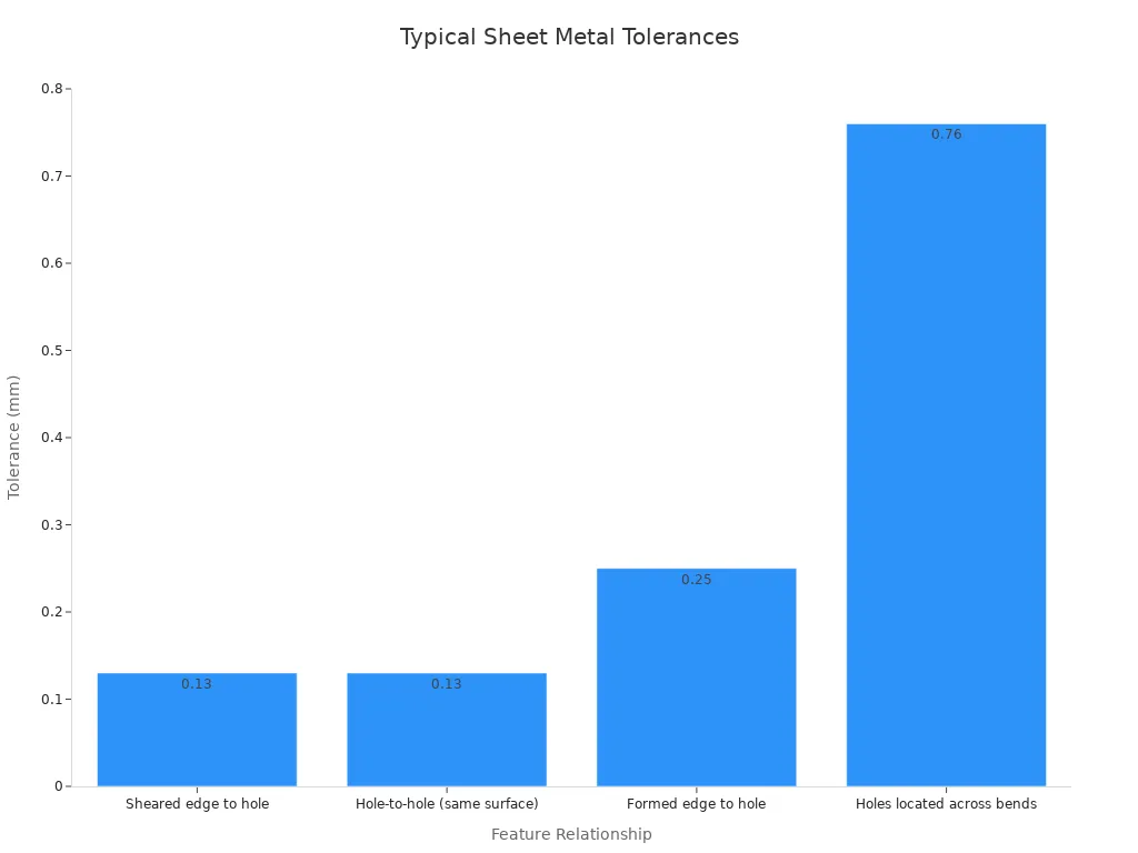
Formed features cannot hold the same tolerances as cut features. Bending introduces springback that varies with material properties, thickness, grain direction, and tooling condition. Cut features are produced while the material remains flat. Formed dimensions inherit the variation of every bend they cross.
The table below shows typical shop-level default tolerances for different feature relationships.
|
Feature Relationship |
Typical Shop-Level Default Tolerance |
|---|---|
|
Sheared edge to hole |
±0.13 mm |
|
Hole-to-hole (same surface) |
±0.13 mm |
|
Formed edge to hole |
±0.25 mm |
|
Holes located across bends |
up to ±0.76 mm (natural forming distortion) |
These values differ between fabrication shops. You should verify them before finalizing your drawings. Using such default tolerance tables helps you avoid over-dimensioning and supports smoother, more efficient manufacturing.
The table below summarizes typical default tolerances by feature type.
|
Feature Type |
Typical Default Tolerance |
|---|---|
|
Laser-cut features |
±0.005″–0.010″ |
|
Formed dimensions (material/bend-count dependent) |
±0.010″–0.030″ |
|
Bend angles |
~±1° |
|
Assemblies and weldments |
Wider (due to welding distortion and part-to-part stack-up) |
You should match the tolerance to the feature type. Cut features can carry the tightest requirements. Formed dimensions need realistic bending windows. Across-bend and assembly dimensions generally need wider tolerances.
Experience shows that setting unnecessarily tight tolerances increases costs without improving performance. The best practice is to define tolerances only as tight as needed for function, safety, and assembly.
Define tolerances based on functional needs, not perfection. Account for material behavior, machine accuracy, and process interactions. Invest in proper inspection methods and maintain machines to sustain long-term quality.
Several common mistakes can undermine your tolerance strategy. Misreading or misapplying standards occurs when designers or operators misinterpret standard codes or apply the wrong tolerance grade. Clear notes and one ruleset per drawing solve most of this. Inaccurate measurements from poorly calibrated tools or inconsistent techniques lead to false results. Regular calibration and standardized inspection procedures are essential. Ignoring material and machine effects—failing to consider springback, thermal expansion, or tool wear—leads to inaccurate assumptions about part accuracy. Small process notes on the drawing or traveler prevent these traps.
Implementing preventive maintenance, training staff on standards, and using modern digital inspection tools minimize mistakes. Proactive quality control saves costs and ensures consistent output.
Tighter tolerances do not always mean better-quality parts. Extremely tight tolerances can increase cost and slow production. You should apply precision where it adds value and relax requirements where it does not. This approach yields precision where it matters while avoiding unnecessary cost, rework, and lead time.
Effective specification of Sheet Metal Tolerances requires you to think critically about each dimension. You must separate critical from conventional, match the tolerance to the feature type, and communicate your intent clearly. These practices help you achieve the best balance of precision and economy.
Tight tolerances raise cost at every stage of production. You must weigh process choice, inspection effort, and scrap risk against the precision your part truly needs.
Your process choice sets the cost baseline. Sheet metal fabrication typically holds ±0.1 mm to ±0.5 mm, while CNC machining reaches ±0.025 mm with minimal setup cost. Sheet metal wins at higher volumes, where tooling costs amortize across many parts. Complex bends may require custom dies or fixtures, which add upfront expense.
|
Aspect |
Sheet Metal Fabrication |
CNC Machining |
|---|---|---|
|
Achievable tolerance |
±0.1 mm to ±0.5 mm |
As tight as ±0.025 mm |
|
Tooling/setup cost |
Custom dies or fixtures for complex bends |
Minimal specialized tooling |
|
Best-fit volume |
Higher volumes |
Low-volume prototyping |
Tighter specifications slow production and demand precise tool setups. Strict bend angle tolerances alone can add 30–60% to bending cost.
Tighter tolerances increase inspection rigor and labor time. You may need specialized fixturing and multiple measurements using calipers, height gauges, CMMs, or go/no-go gauges. Statistical process control (SPC) tracks variation over a production run and catches drift before parts fail.
Tight flatness or overall dimensional tolerances raise fabrication time and scrap rates. Every rejected part wastes material, machine time, and labor. Over-tolerancing amplifies this waste. Apply tight tolerances only to critical features.
You can cut cost without sacrificing function. Specify standard bend radii of 1–1.5x material thickness to avoid special tooling. Replace welded joints with formed features like flanges, tabs, and embossments. Optimize flat patterns to nest within standard sheet sizes and reduce material waste by 20–30%. Choose standard hardware such as PEM nuts and studs. Conduct Design for Manufacturing (DFM) reviews early to quantify trade-offs.
This case study shows how tolerance decisions affect real project budgets. You can apply the same lessons to your own enclosure designs.
An engineer submitted an enclosure panel drawing with a bend angle tolerance of ±0.25° and a flange tolerance of ±0.005 inches. These values mirror machining limits, not forming limits. The panel also carried ±0.005 inches across four bends. That stack-up demanded secondary machining on every flange. The quoted price reflected the extra operations, slower press brake cycles, and full CMM inspection.
HPS engineers reviewed the drawing before production. They asked one question: which dimensions control fit and function? The answer was simple. Only the mounting hole pattern and the cover interface mattered. HPS proposed a revised tolerance scheme. The team kept ±0.005 inches on the laser-cut hole pattern. They relaxed the bend angle to ±1.0° and the flange length to ±0.015 inches. Standard press brake tooling replaced the custom setup.
The revised drawing cut unit cost by 28% and lead time by five days. Scrap dropped from 6% to under 1%. The panel passed first article inspection without rework. You gain the same benefits when you separate critical features from cosmetic ones. HPS delivers this balance through in-house laser cutting, precision forming, and expert tolerance guidance.
You achieve precision sheet metal tolerances when you prioritize critical features by function, not arbitrary tightness. Allow standard tolerances (±0.030 in.) on non-critical dimensions to reduce costs. HPS delivers precision down to ±0.005 inches on laser-cut parts with expert guidance. Collaborate early with design, manufacturing, and procurement to avoid rework. Always verify through first article inspection and clear documentation.
HPS achieves ±0.005 inches (±0.13 mm) on laser-cut profiles and holes. You get this precision through in-house fiber laser cutting and strict process control.
You should relax bend tolerances when a feature does not affect fit or assembly. Standard forming holds ±1.0° on bend angles and ±0.030 inches on flange lengths.
HPS reviews your drawing before production and identifies over-toleranced features. The team recommends realistic values that protect function while cutting unnecessary inspection and machining costs.
 지금 견적을 받으세요


메시지를 남겨주세요
Wechat으로 스캔 :

WhatsApp으로 스캔 :

Hi! Click one of our members below to chat on

 English
 Français
 Deutsch
 Русский
 Italiano
 Español
 Nederland
 日语
日语 한국어
한국어 Svenska
 IPv6 네트워크 지원